Step 1: Make an INS. Step 2: Profit
- sidharthtalia
- Jan 6, 2021
- 9 min read
Updated: Dec 1, 2021
Preface:
Near the end of last year (2020), I decided to take the knowledge and insights I had in the domain of state estimation from prior work and condense them into a single system. This motivation came out of my frustration with the existing approaches at the low-cost-end and the high cost of the professional-end. It felt like if you wanted to get from point A to B, you could either build your own car or buy a Lamborghini. I wanted something that was in between these two options, and I saw an opportunity to learn something along the way.
I'm doing this project to teach myself, apart from inertial navigation systems, product development cycles, taxes, finances, business models, and so forth. The exercise here isn't (just) to make an inertial navigation system, the exercise is to figure out the business side of the tech industry. The inertial navigation system is a placeholder for something to sell. I chose inertial navigation systems because I'm passionate about them and working on them doesn't feel like a burden to me.
You might notice that the structure of this blog looks something like:
Introduction
Problem
Prior art exhibit 1 which is discarded pretty easily
Prior art exhibit 2 from Loser et. al. which is used as a benchmark
My approach, contribution
Results and discussion (and mentioning future directions).
Introduction:
For any robot, knowing where it is, how fast it is moving, and how it is oriented in the world is of utmost importance. This information usually comes from a "state-estimator". However, making a reliable state estimator usually takes some time. For instance, in my mini-self-driving-car project, I spent roughly 4 months testing and debugging the state estimator to make sure GPS glitches and inaccuracies didn’t affect it. I would prefer a "Plug and Play (PnP)" solution in the future.
For outdoor robotics, the most general PnP solution for this problem is a “GNSS-aided Inertial Navigation System”, or GNSS-INS for short. GNSS(or GPS) based systems are still relevant in the age of LIDAR and computer vision-based positioning because one, you can’t use LIDAR/CV for high altitude aerial vehicles, ground vehicles in an open desert, or marine vehicles out at sea. Two, GNSS-based positioning technology is far more mature as compared to LIDAR or computer vision-based positioning and is still improving day by day, now that we have far more positioning satellites than we did before.
The problem
There are many companies that manufacture commercial and industrial grade INS. Vectornav, SBG, and InertialSense are some examples. So if these are already produced by well-established companies, why didn’t I just buy one from them? Well, because these systems are expensive. Like "2000 US dollars per unit" expensive. Here’s a list of quotes for these systems.
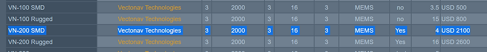
Note that some systems in the list like the ACME Daisy-7 only contain the sensors and do not provide solutions for navigation themselves and are thus cheaper.
Aren’t there ROS packages for this already?
Yes and no. While ROS does provide a sensor fusion backend, this backend
Requires an IMU sensor that provides absolute heading, which is affected by the IMU's roll and pitch estimates. Such IMU sensors use accelerometer-gyroscope fusion for orientation estimation. This approach for orientation estimation is susceptible to divergence under large accelerations induced by maneuvering. Since these IMUs have no position velocity feedback, they are also susceptible to divergence under continuous magnetic interference (think operating near power lines).
Filters the orientation data using the reported body rates from the IMU but it doesn't estimate the biases, which can grow unpredictably with time.
Does not account for the time delay in the GPS data, which is important for highly dynamic applications. The GPS reported position corresponds to a position ~100-250 ms in the past.
Okay, but what if I just take px4/ardupilot and use that as an INS?

I say that because I once did the same thing. For those who don't know, px4 and ardupilot are both open-source multi-platform autopilot software stacks used by thousands of people for making all sorts of unmanned systems (small scale usually). Naturally, the autopilot needs a navigation system, so it may seem obvious after some thought that the system could be repurposed as a navigation system.
I faced the issues described in the previous section as a part of the DLive self-driving car group at IIT-Delhi. At the time, I used a ublox M8N GPS and a pixhawk running ardupilot as an inertial navigation system.
However, we still had to post-process the pixhawk’s output and fiddle with its parameters to make it sort of work for us (version 3.6 glitched a bit back then). The cost of the hardware was 300ish dollars all-inclusive (taxes and import duties too), but it took someone with prior experience with these things to integrate it into the project. Apart from me, there wasn't anyone in the team who understood what I was doing. I realized that not everyone has the time, interest, or capability to understand these systems and repurpose them.
Well, how hard can it be?
My goal here was to develop a PnP INS which:
uses a generalized motion model which uses quaternions instead of Euler angles, and a mathematically rigorous Extended Kalman Filter implementation.
has solution quality equivalent or better than that of Ardupilot running on the pixhawk.
is reasonably priced for the solution quality.
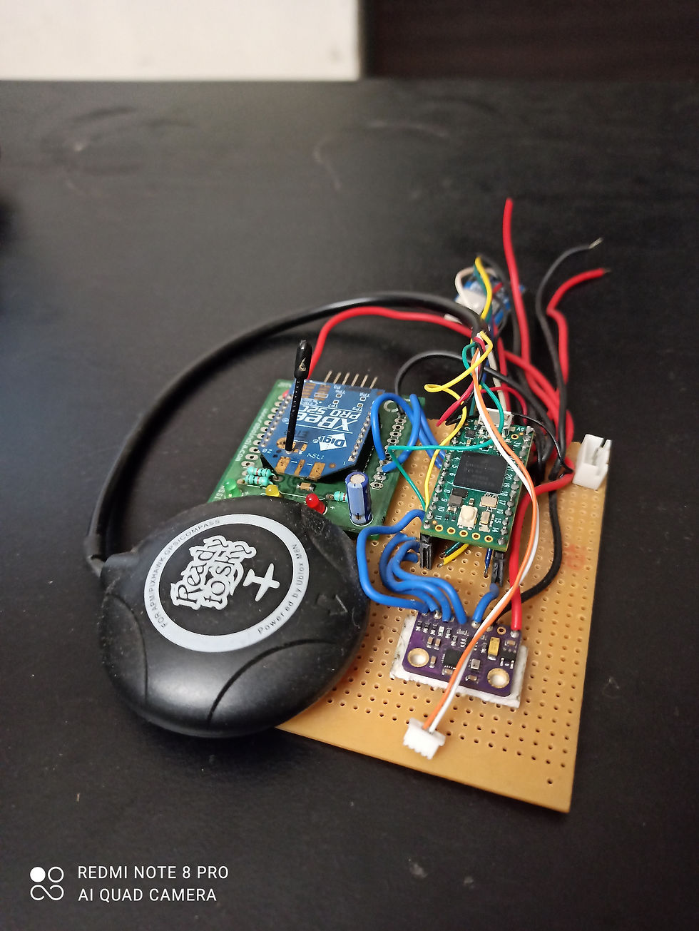
For the prototyping stage, I used a teensy 4.0 microcontroller, a single IMU, compass, barometer, and a Ublox M8N(72-channel GPS). The Teensy 4.0 is quite expensive, but it has a lot of processing power, which is useful in the initial stages for tinkering. My performance targets for the final system (1 sigma std. dev.) were:
+/- 0.05 > degrees of static roll-pitch accuracy > +/- 0.03
+/- 0.2 > degrees static heading accuracy > +/- 0.10
+/- 0.2 > degrees of dynamic roll-pitch accuracy > +/- 0.05
+/- 0.2 > degrees of dynamic heading accuracy > +/- 0.05
Loop closure accuracy of < 1 m horizontal
Loop rate of 500 Hz
For reference, you can refer to the performance numbers (1 sigma) for Vectornav VN-200
The system is divided into two parts. An attitude heading reference system (AHRS) and a full state estimator (or the main INS).
The AHRS:
Fuses the IMU and the magnetometer data to find the orientation.
Is used internally for boot-strapping and sanity checking the INS during the first few seconds after initialization or a reset.
Is not severely affected by maneuvering when GPS fixes are available as it compensates for the centrifugal accelerations.
Can withstand intermediate/short-term magnetic interference.
Provides data on the output stream for use in mostly static or slow-moving applications.
The way that the AHRS avoids being affected by magnetic interference and accelerations from maneuvering is that it changes the sensor noise figures so that the measurements no longer affect the estimate as long as there is an interference of some sort. That is the easy part. The hard part is detecting the interference cases accurately.
For the full state estimator (INS), instead of writing everything from scratch as in my previous projects, I took inspiration from the state estimators used in ardupilot/px4, because that was the benchmark to beat. I could have gone with the legacy uNavINS which has been used in data collection systems by NASA and is readily implemented on the Teensy 4.0 (Note that the latest version of uNavINS is available here). However, I prefer an implementation where each matrix multiplication is written out line by line, allowing me to create a highly bespoke system. In case you want to create your own INS, the uNavINS is a pretty good candidate for doing so. Currently, my INS:
Estimates the 3D position, velocity, and the quaternion of the orientation
Estimates the accelerometer and gyroscope run-time biases
Estimates body frame magnetic field and world frame magnetic field. These are used in conjunction with world magnetic data for rejecting interference near power lines*
Can accept external velocity measurements for improving odometry*
The points marked with a * at the end are features that the InertialNav backend does not provide by default.
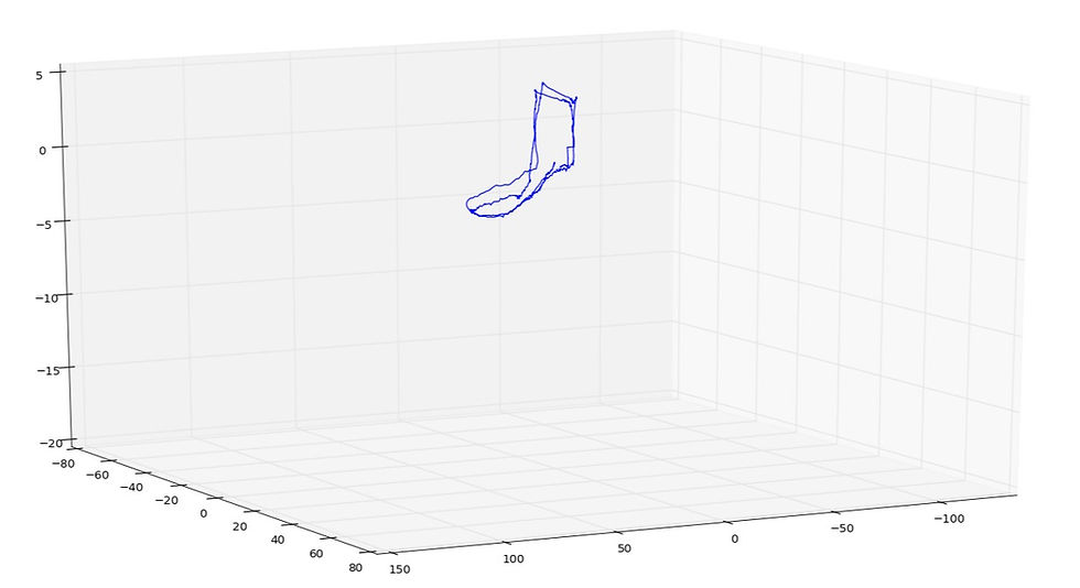
The following graphs show the first "sanity" checks of the system I made. The sanity check ensures that the loop closure error is within reasonable bounds. I put the system on the dashboard of my car and drove around in a loop. This test was conducted near a high tension line and underground steel rails. The first graph shows the top-down view and the second graph shows a side-view to check that the altitude estimate is also convergent. Note that the units are in meters.

The code was first tested on a perf-board circuit (Fig 6) and later on a custom PCB (Fig 9). On the Teensy 4.0, the loop update rate was 1600 Hz. This was better than the 500 Hz I was aiming for, but the Teensy is expensive (we have hefty import duties!) and I would rather put that money towards a 92-channel GPS in place of a 72-channel one.


Fig 9: First PCB iteration of the system. I used aluminum foil for the GPS ground plane
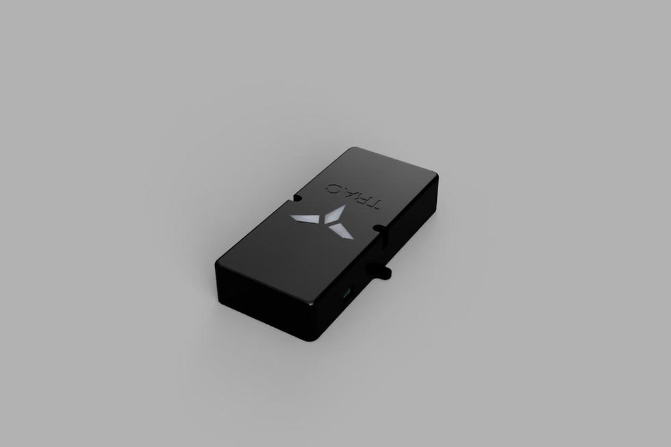
Project TRAC Cerberus
For the final version, I decided to shift to the ESP32 processor. It costs 1/8th of what the teensy costs. This also meant speeding up the code because the ESP32 is ~7 times slower (coremark of 351, according to this benchmark which my tests agreed with). I used the teensy system as a benchmark to ensure that the optimizations didn’t affect the reliability. Once satisfied with the performance and reliability, it was time for testing and comparisons.
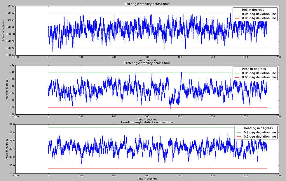
The graph below shows the static stability of the AHRS output over the period of roughly 1 hour:
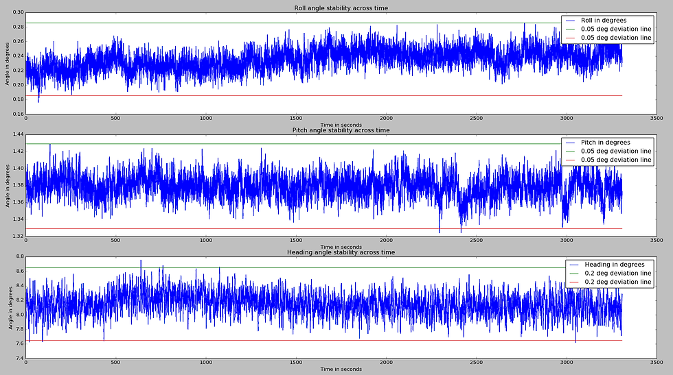
The red and green straight lines are deviation lines. I use them to see if the estimated diverged by more than the set limit at any point during the test. One or two instances of overstepping are acceptable. The 1-sigma standard deviation for the 1-hour test comes out to be:
roll: 0.0136 degrees
pitch: 0.0124 degrees
heading: 0.1378 degrees
The system was also tested at an arbitrary large-angle orientation for ~10 minutes to ensure that this static stability was the same for any orientation:
The 1-sigma standard deviation comes out to be:
roll: 0.0167 degrees
pitch: 0.0154 degrees
heading: 0.108 degrees
Note that the standard deviation in the random angle test appears smaller because it was conducted for a smaller duration of time. I couldn't keep it in the same orientation for longer than 10 minutes but if someone really insists I will do an hour-long test too.
Next, I checked the loop-closure accuracy of the system in the same area as before. The system was placed on the dashboard of my car.
The car was being driven by me and I was trying to go over the same patch on the straight section of the road repeatedly. The loop-closure accuracy can be seen as the gap between the subsequent trajectories in the straight section that cuts the 10x10 meter grid.
After this sanity check, I collected data from the pixhawk running Arduplane(4.0.9) with a ublox M8N GPS, using the default parameters.

The green arrows represent the estimate from the pixhawk, whereas the yellow arrows represent the orientation from Cerberus. Note that the initial orientation of both systems is off due to the magnetic interference. Both systems have a similar loop-closure capability. This test is a sanity check to ensure that my system performs at least as well as a pixhawk. In earlier versions of ardupilot, there used to be a glitch when the vehicle started moving which could be sorted out with some parameter adjustments. Version 4.0.9 doesn't have that thankfully.
From the same test, we can also get the dynamic orientation accuracy by taking the difference between the roll/pitch/heading data and the centerline of the same data.
The centerline is found by Gaussian filtering the data with a sigma = 2. A smaller sigma will result in not enough filtering and a larger sigma will result in the magnitude being attenuated too far. Fig 15 shows an example case where noise is added to a 20 Hz sinusoidal signal (original) and different levels of Gaussian filtering are applied. The filtered result should resemble the original sinusoidal signal:
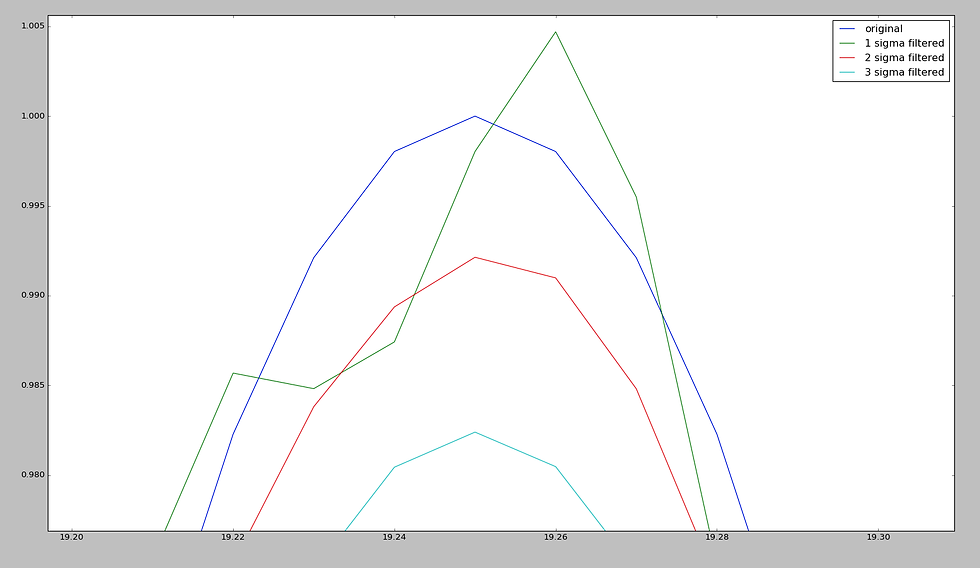
Fig. 16 shows the roll/pitch/yaw error for the pixhawk data corresponding to the test shown above:
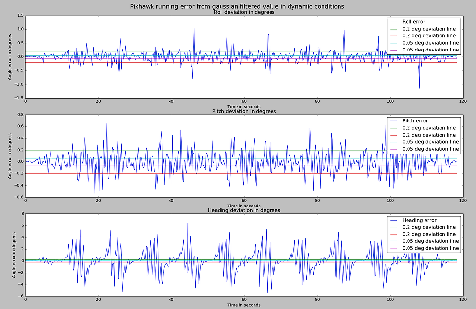
Note that the graphs show the error in roll/pitch/heading and not the roll/pitch/heading itself. The straight lines shown in the graph are the deviation lines I use for sanity checking. The 1 sigma standard deviation comes out to be:
roll: 0.1914 degrees
pitch: 0.1759 degrees
yaw: 0.4485 degrees
Fig. 17 shows the roll/pitch/heading error for my system:
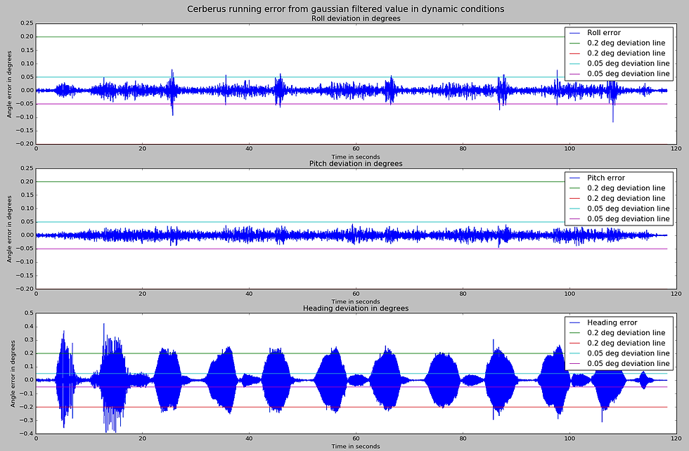
It appears to be within the boundaries I set for this system. The 1 sigma standard deviation comes out to be:
roll: 0.01132 degrees
pitch: 0.0091 degrees
yaw: 0.081 degrees
I prefer to use the deviation lines as they tell you whether the system's error ever became larger than a certain threshold. If the maximum spread of the error on one side is bounded to some limit 'E', the 1-sigma standard deviation will be less than or equal to 'E'.
Note that this method's result should be taken with a grain of salt (and maybe pepper too):
This method assumes:
Estimated orientation = True orientation + Noise
and that applying a gaussian filter reveals the true orientation. However, when we plot the data from both the systems together (with the real-world orientation difference being accounted for), we see that the two systems actually produce a slightly different output.
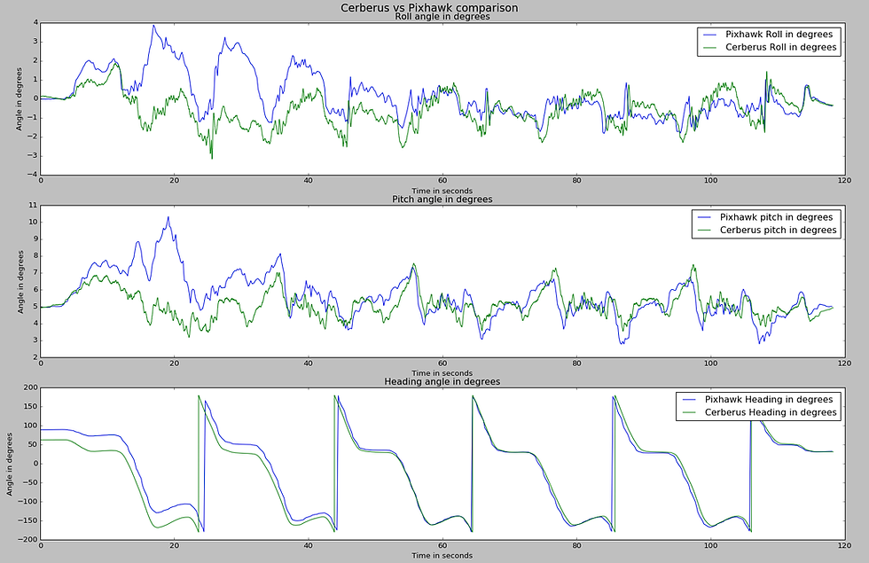
You can tell that the pixhawk's initial data is wrong because the large roll-pitch changes in the 20-40 second window indicate that I drove my car into a ditch and broke my spine. In the heading angle graph, you can see how "wavy" pixhawk's output is.
Additionally, I also wanted external velocity fusion. This feature is particularly useful for combining data from visual odometry or lidar-based odometry. This may be useful on smaller ground vehicles that have tighter tolerances to work with. In the following demo, I was pulling figure 8’s on my roof and trying my best to pass through the same point repeatedly:
The car used here is the MuSHR car, using an intel t265 for velocity measurements. The orientation on rviz is off because of a bug that I hadn't fixed at the time. Unfortunately, after this test, the jetson nano on the car went kaput so I couldn't do any more testing with the debugged interface code.
The interface code and the data for these tests are available here.
This concludes my blog about the inertial navigation system, if you made it this far and liked it, or have suggestions, let me know on LinkedIn! Oh, and as for the price, I haven't decided yet. My approach to finding the right price is to do a POC round and take feedback from the users about the highest price they'd be willing to pay for it. Then sell it for half of that. Simple enough innit?


Comments